

وصف
جدول المحتويات
- Specifications of 904L Stainless Steel Flanges
- Size Range of SS 904L Flanges (in Inches)
- Chemical Composition of ASME SA182 904L Weld Neck Raised Face Flanges
- Mechanical & Physical Characteristics of DIN 1.4539 904الشفاه L
- Variety of Industrial Flanges Made from UNS N08904 الفولاذ المقاوم للصدأ
- 904L Stainless Steel Flange Equivalent Grades and Standards
- Thermal Properties of DIN 1.4539 Ring-Type Joint Flanges
- Applications of Stainless Steel F904L Flanges
- Physical Parameters of 904L Stainless Steel Flanges
- Weight Chart for ASTM A182 F904L Long Weld Neck Flanges
- ANSI B16.5 F904L Ring Type Joint Flange Dimension Chart
- Pressure Rating Details for Stainless Steel F904L Weld Neck Flanges
شفة الفولاذ المقاوم للصدأ
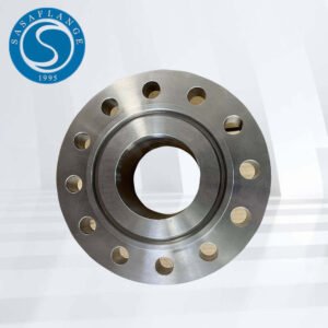
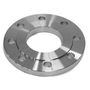
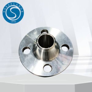
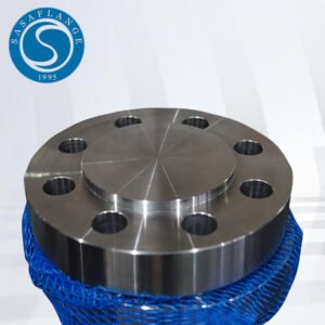
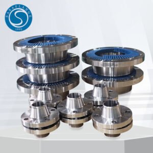
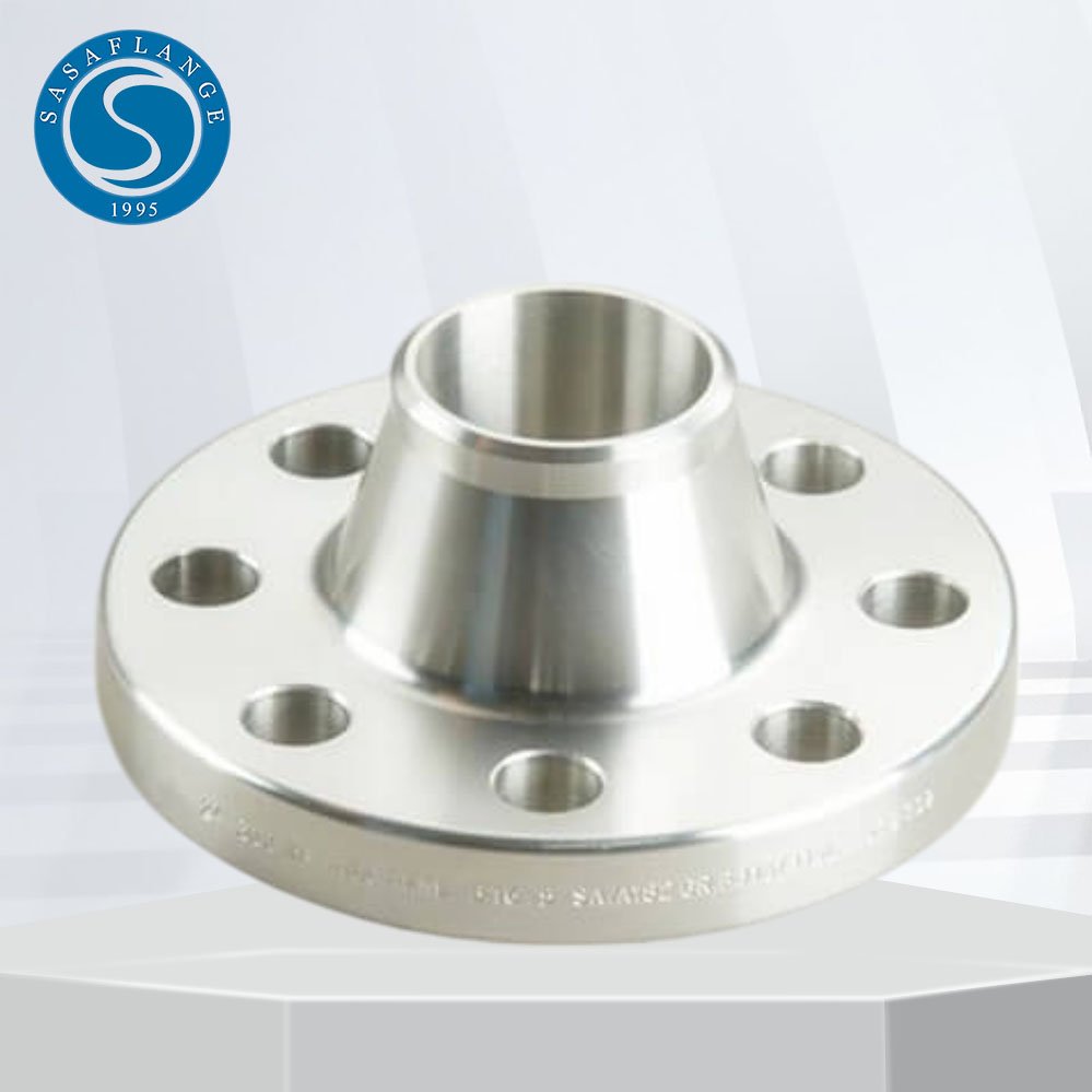
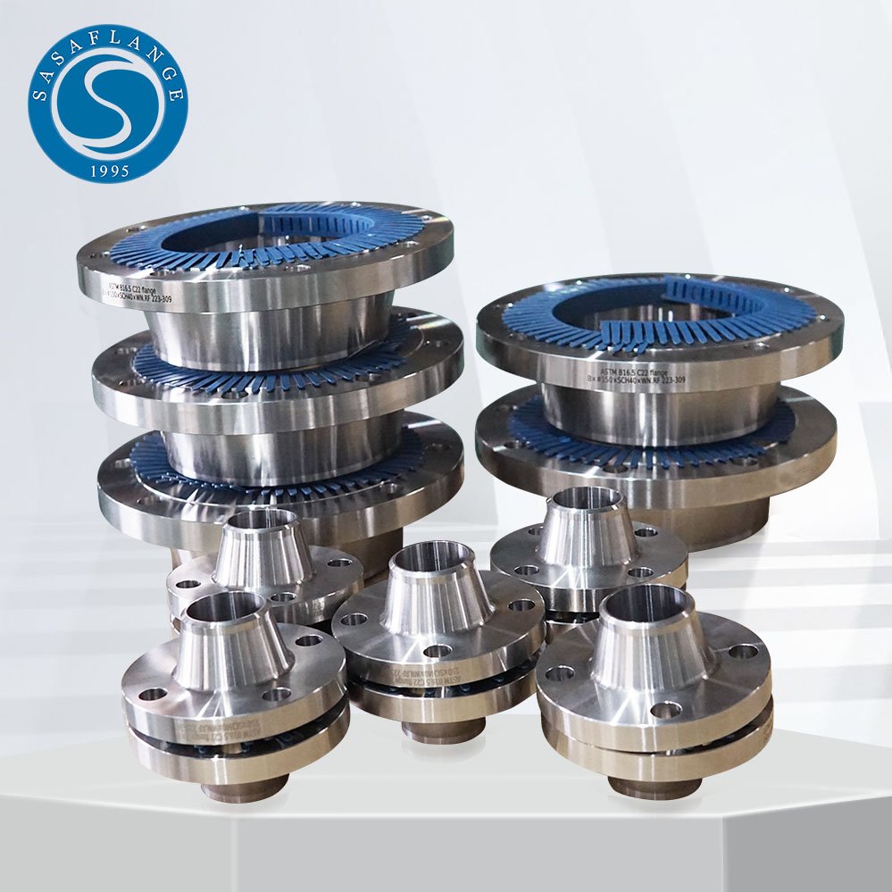
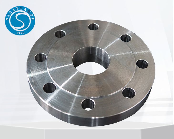
904L stainless steel flanges are high-alloy components designed for use in highly corrosive environments. Manufactured from UNS N08904 (DIN 1.4539), these flanges offer exceptional resistance to strong reducing acids such as sulfuric acid, as well as excellent performance against chloride-induced pitting and crevice corrosion. With low carbon content and added copper, 904L flanges maintain strength while preventing intergranular corrosion after welding. يتم استخدامها على نطاق واسع في المعالجة الكيميائية, التطبيقات البحرية, المستحضرات الصيدلانية, and pollution control equipment. Available types include weld neck, أعمى, سهل الارتداء, لحام المقبس, مفصل اللفة, والشفاه الخيوط, conforming to standards such as ASTM A182 and ANSI B16.5. Their durability and corrosion resistance make them ideal for critical piping systems in aggressive environments.
Specifications of 904L Stainless Steel Flanges
| تحديد | ASTM A182 / أسمي SA182 |
|---|---|
| فصل | 150#, 300#, 600#, 900#, 1500#, 2500#, PN6, PN10, PN16, PN25, بي إن 40, PN64 الخ. |
| مقاس | 1/2″ (15 ملحوظة:) إلى 48″ (1200ملحوظة:) |
| المعايير | أنسي/ASME B16.5, ب16.48, BS4504, ب 16.47 السلسلة أ & ب, بكالوريوس 10, إن-1092, DIN, إلخ. |
Size Range of SS 904L Flanges (in Inches)
| حجم الأنبوب الاسمي | القطر الخارجي للشفة | سمك شفة | قطر الوجه المرفوع | قطر المحور عند القاعدة | الطول من خلال المحور | القطر أو التجويف | قطر المحور في شطبة | نصف قطر فيليه | عمق المقبس | |||
|---|---|---|---|---|---|---|---|---|---|---|---|---|
| لحام الرقبة | الانزلاق على مقبس مترابطة | اللفة المشتركة | الانزلاق على المقبس | اللفة المشتركة | ||||||||
| يا | س | ر | X | ي | ي | ي | دبليو | ب | ح | ص | ز | |
| 1/2 | 3-1/2 | 7/16 | 1-3/8 | 1-3/16 | 1-7/8 | 5/8 | 5/8 | .88 | .90 | .84 | 1/8 | 3/8 |
| 3/4 | 3-7/8 | 1/2 | 1-11/16 | 1-1/2 | 2-1/16 | 5/8 | 5/8 | 1.09 | 1.11 | 1.05 | 1/8 | 7/16 |
| 1 | 4-1/4 | 9/16 | 2 | 1-15/16 | 2-3/16 | 11/16 | 11/16 | 1.36 | 1.38 | 1.32 | 1/8 | 1/2 |
| 1-1/4 | 4-5/8 | 5/8 | 2-1/2 | 2-5/16 | 2-1/4 | 13/16 | 13/16 | 1.70 | 1.72 | 1.66 | 3/16 | 9/16 |
| 1-1/2 | 5 | 11/16 | 2-7/8 | 2-9/16 | 2-7/16 | 7/8 | 7/8 | 1.95 | 1.97 | 1.90 | 1/4 | 5/8 |
| 2 | 6 | 3/4 | 3-5/8 | 3-1/16 | 2-1/2 | 1 | 1 | 2.44 | 2.46 | 2.38 | 5/16 | 11/16 |
| 2-1/2 | 7 | 7/8 | 4-1/8 | 3-9/16 | 2-3/4 | 1-1/8 | 1-1/8 | 2.94 | 2.97 | 2.88 | 5/16 | 3/4 |
| 3 | 7-1/2 | 15/16 | 5 | 4-1/4 | 2-3/4 | 1-3/16 | 1-3/16 | 3.57 | 3.60 | 3.50 | 3/8 | 13/16 |
| 3-1/2 | 8-1/2 | 15/16 | 5-1/2 | 4-13/16 | 2-13/16 | 1-1/4 | 1-1/4 | 4.07 | 4.10 | 4.00 | 3/8 | 7/8 |
| 4 | 9 | 15/16 | 6-3/16 | 5-5/16 | 3 | 1-5/16 | 1-5/16 | 4.57 | 4.60 | 4.50 | 7/16 | 15/16 |
| 5 | 10 | 15/16 | 7.5/16 | 6-7/16 | 3-1/2 | 1-7/16 | 1-7/16 | 5.66 | 5.69 | 5.56 | 7/16 | 15/16 |
| 6 | 11 | 1 | 8-1/2 | 7-9/16 | 3-1/2 | 1-9/16 | 1-9/16 | 6.72 | 6.75 | 6.63 | 1/2 | 1-1/16 |
| 8 | 13-1/2 | 1-1/8 | 10-5/8 | 9-11/16 | 4 | 1-3/4 | 1-3/4 | 8.72 | 8.75 | 8.63 | 1/2 | 1-1/4 |
| 10 | 16 | 1-3/16 | 12-3/4 | 12 | 4 | 1-15/16 | 1-15/16 | 10.88 | 10.92 | 10.75 | 1/2 | 1-5/16 |
| 12 | 19 | 1-1/4 | 15 | 14-3/8 | 4-1/2 | 2-3/16 | 2-3/16 | 12.88 | 12.92 | 12.75 | 1/2 | 1-9/16 |
| 14 | 21 | 1-3/8 | 16-1/4 | 15-3/4 | 5 | 2-1/4 | 3-1/8 | 14.14 | 14.18 | 14.00 | 1/2 | 1-5/8 |
| 16 | 23-1/2 | 1-7/16 | 18-1/2 | 18 | 5 | 2-1/2 | 3-7/16 | 16.16 | 16.19 | 16.00 | 1/2 | 1-3/4 |
| 18 | 25 | 1-9/16 | 21 | 19-7/8 | 5-1/2 | 2-11/16 | 3-13/16 | 18.18 | 18.20 | 18.00 | 1/2 | 1-15/16 |
| 20 | 27-1/2 | 1-11/16 | 23 | 22 | 5-11/16 | 2-7/8 | 4-1/16 | 20.20 | 20.25 | 20.00 | 1/2 | 2-1/8 |
| 24 | 32 | 1-7/8 | 27-1/4 | 26-1/8 | 6 | 3-1/4 | 4-3/8 | 24.25 | 24.25 | 24.00 | 1/2 | 2-1/2 |
Chemical Composition of ASME SA182 904L Weld Neck Raised Face Flanges
| درجة | ج | من | و | ص | س | كر | شهر | في | النحاس |
| SS 904L | 0.020 الأعلى | 2 الأعلى | 1.00 الأعلى | 0.040 الأعلى | 0.030 الأعلى | 19.00 - 23.00 | 4.00 - 5.00 الأعلى | 23.00 - 28.00 | 1.00 - 2.00 |
Mechanical & Physical Characteristics of DIN 1.4539 904الشفاه L
| كثافة | نقطة الانصهار | قوة الشد | قوة العائد (0.2%إزاحة) | استطالة |
| 7.95 جم/سم3 | 1350 درجة مئوية (2460 درجة فهرنهايت) | رطل لكل بوصة مربعة – 71000 , ميجاباسكال – 490 | رطل لكل بوصة مربعة – 32000 , ميجاباسكال – 220 | 35 % |
Variety of Industrial Flanges Made from UNS N08904 الفولاذ المقاوم للصدأ
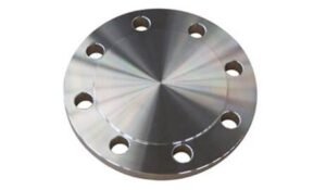 | 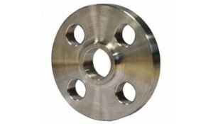 | 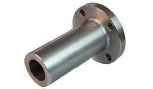 | 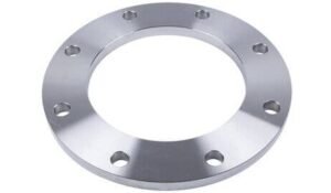 |
| الشفاه العمياء | الشفاه المشتركة اللفة | الشفاه طويلة الرقبة اللحام | الشفاه لوحة |
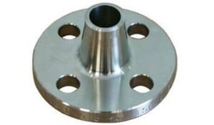 | 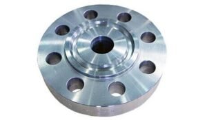 | 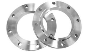 | 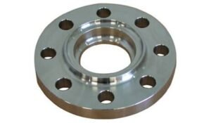 |
| تقليل الشفاه | الشفاه المشتركة من النوع الدائري | الانزلاق على الشفاه | الشفاه لحام المقبس |
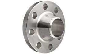 | 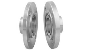 | 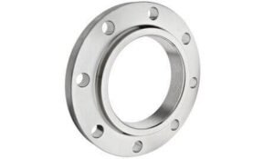 | 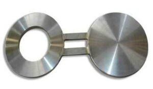 |
| لحام الشفاه الرقبة | لسان & الشفاه الأخدود | مترابطة / الشفاه مشدودة | النظارات العمياء الشفاه |
904L Stainless Steel Flange Equivalent Grades and Standards
| معيار | رقم المادة. | نحن | JIS | بكالوريوس | KS | أفنور | EN |
| SS 904L | 1.4539 | N08904 | SUS 904L | 904S13 | STS 317J5 | Z2 NCDU 25-20 | X1NiCrMoCu25-20-5 |
Thermal Properties of DIN 1.4539 Ring-Type Joint Flanges
DIN 1.4539, also known as Alloy 904L or UNS N08904, is an austenitic stainless steel designed for exceptional corrosion resistance, particularly in aggressive environments. When used in حلقة من النوع المشترك (آر تي جيه) الشفاه, its thermal properties are critical for ensuring sealing performance and dimensional stability under varying temperature conditions.
| ملكية | قيمة | ملحوظات |
|---|---|---|
| الموصلية الحرارية (at 20°C) | ~12.0 W/m·K | Lower than carbon steel, typical of austenitic SS |
| Specific Heat Capacity (at 20°C) | ~500 J/kg·K | High thermal inertia, suitable for stable operation |
| Coefficient of Thermal Expansion | ~16.5 µm/m·K (from 20–100°C) | Important for gasket fit in RTJ sealing surfaces |
| نطاق الذوبان | 1300 – 1390°C | Indicates safe upper limit for high-temp service |
| Maximum Continuous Service Temp | ~400°C (in oxidizing environments) | Beyond this, corrosion resistance may reduce |
| Thermal Shock Resistance | معتدل | Preheating and slow cooling are recommended in cyclic heating scenarios |
These thermal characteristics make DIN 1.4539 RTJ flanges ideal for high-temperature, high-pressure sealing applications in chemical processing, مصفاة, and offshore installations, where thermal cycling and aggressive media are present. Proper design allowances for expansion and thermal stress are essential to maintain joint integrity.
Applications of Stainless Steel F904L Flanges
مصانع المعالجة الكيميائية
Resistant to strong acids such as sulfuric, phosphoric, وأحماض الخليك, 904L weld neck flanges are ideal for piping systems handling corrosive fluids.زيت & Gas Refineries
Used in offshore and onshore installations, especially where resistance to chloride-induced stress corrosion cracking is required.محطات تحلية المياه
Excellent performance in high-chloride environments makes them suitable for seawater treatment and desalination piping systems.الصيدلانية & Food Processing Industries
Non-reactive and hygienic surface properties make F904L flanges suitable for clean-in-place (CIP) systems and sterile fluid pipelines.اللب & Paper Industry
Used in bleach plants and acidic process lines due to their resistance to oxidizing media.الهندسة البحرية
Preferred in shipbuilding and offshore platforms due to their durability in saline water environments.Pollution Control Equipment
Employed in flue gas desulfurization (مجموعة التركيز) أنظمة, especially in scrubber assemblies and acid gas lines.
Physical Parameters of 904L Stainless Steel Flanges
| ملكية | قيمة | وصف |
|---|---|---|
| كثافة | 8.0 جم/سم3 (8000 kg/m³) | High-density material suitable for pressure retention |
| معامل المرونة | ~200 GPa (at 20°C) | Indicates good rigidity and deformation resistance |
| Poisson’s Ratio | ~0.30 | Ratio of lateral to axial strain |
| الموصلية الحرارية | ~12 W/m·K (at 20°C) | Lower than carbon steel; affects heat dissipation rate |
| Specific Heat Capacity | ~500 J/kg·K (at 20°C) | Reflects energy required to raise temperature |
| Electrical Resistivity | ~0.95 µΩ·m | Higher than common stainless grades, reducing galvanic effects |
| Magnetic Permeability | ~1.0 (non-magnetic in annealed condition) | Suitable for non-magnetic applications |
| نطاق الذوبان | 1300 – 1390°C | Relevant for welding and high-temperature environments |
Weight Chart for ASTM A182 F904L Long Weld Neck Flanges
ملحوظة: قد يختلف الوزن الفعلي قليلاً حسب الأبعاد الدقيقة, سمك شفة, طول الرقبة, والتسامح التصنيع.
| Pipe Normal Diam. | O.D. شفة | Thk. Of Flange Min | Diam. ل مَركَز | قطر الوجه المرفوع | Length Hub.Y | Thread Length | Diam. of Bolt Circle | Diam. of Bolt Holes | Number of Bolts | Diam. ل البراغي (بوصة) | KG | رطل | |
|---|---|---|---|---|---|---|---|---|---|---|---|---|---|
| بوصة | dn | يا | ج | X | ز | ي | ت | قبل الميلاد | BH | BN | BD | ||
| 1/2″ | 15 | 89.00 | 11.20 | 30.20 | 35.10 | 15.70 | 15.70 | 60.50 | 15.80 | 4 | 1/2″ | 0.4 | 0.9 |
| 3/4″ | 20 | 98.50 | 12.70 | 38.10 | 42.90 | 15.70 | 15.70 | 69.90 | 15.80 | 4 | 1/2″ | 0.7 | 1.5 |
| 1″ | 25 | 108.00 | 14.20 | 49.30 | 50.80 | 17.50 | 17.50 | 79.30 | 15.80 | 4 | 1/2″ | 0.8 | 1.8 |
| 1-1/4″ | 32 | 117.50 | 15.70 | 58.70 | 63.50 | 20.60 | 20.60 | 88.90 | 15.80 | 4 | 1/2″ | 1.2 | 2.6 |
| 1-1/2″ | 40 | 127.00 | 17.50 | 65.00 | 73.20 | 22.40 | 22.40 | 98.60 | 15.80 | 4 | 1/2″ | 1.5 | 3.3 |
| 2″ | 50 | 152.50 | 19.10 | 77.70 | 91.90 | 25.40 | 25.40 | 120.70 | 19.10 | 4 | 5/8″ | 2.3 | 5.1 |
| 2-1/2″ | 65 | 178.00 | 22.40 | 90.40 | 104.60 | 28.40 | 28.40 | 139.70 | 19.10 | 4 | 5/8″ | 3.7 | 8.1 |
| 3″ | 80 | 190.50 | 23.90 | 108.00 | 127.00 | 30.20 | 30.20 | 152.40 | 19.10 | 4 | 5/8″ | 4.1 | 9 |
| 3-1/2″ | 90 | 216.00 | 23.90 | 122.20 | 139.70 | 31.80 | 31.80 | 177.80 | 19.10 | 8 | 5/8″ | 5.1 | 11.2 |
| 4″ | 100 | 228.50 | 23.90 | 134.90 | 157.20 | 33.30 | 33.30 | 190.50 | 19.10 | 8 | 5/8″ | 5.9 | 13 |
| 5″ | 125 | 254.00 | 23.90 | 163.60 | 185.70 | 36.60 | 36.60 | 215.90 | 22.40 | 8 | 3/4″ | 7 | 15.4 |
| 6″ | 150 | 279.50 | 25.40 | 192.00 | 215.90 | 39.60 | 39.60 | 241.30 | 22.40 | 8 | 3/4″ | 8.4 | 18.5 |
| 8″ | 200 | 343.00 | 28.40 | 246.10 | 269.70 | 44.50 | 44.50 | 298.50 | 22.40 | 8 | 3/4″ | 13 | 28.6 |
| 10″ | 250 | 406.50 | 30.20 | 304.80 | 323.90 | 49.30 | 49.30 | 362.00 | 25.40 | 12 | 7/8″ | 18 | 39.5 |
| 12″ | 300 | 482.50 | 31.80 | 365.30 | 381.00 | 55.60 | 55.60 | 431.80 | 25.40 | 12 | 7/8″ | 29 | 64 |
| 14″ | 350 | 533.50 | 35.10 | 400.10 | 412.80 | 57.20 | 57.20 | 476.30 | 28.50 | 12 | 1″ | 39 | 86 |
| 16″ | 400 | 597.00 | 36.60 | 457.20 | 469.90 | 63.50 | 63.50 | 539.80 | 28.50 | 16 | 1″ | 47 | 103 |
| 18″ | 450 | 635.00 | 39.60 | 505.00 | 533.40 | 68.30 | 68.30 | 577.90 | 31.80 | 16 | 1 1/8″ | 57 | 126 |
| 20″ | 500 | 698.50 | 42.90 | 558.80 | 584.20 | 73.20 | 73.20 | 635.00 | 31.80 | 20 | 1 1/8″ | 76 | 167 |
| 24″ | 600 | 813.00 | 47.80 | 663.40 | 692.20 | 82.60 | 82.60 | 749.30 | 35.10 | 20 | 1 1/4″ | 97 | 214 |
ANSI B16.5 F904L Ring Type Joint Flange Dimension Chart
مادة: ASTM A182 F904L (UNS N08904, DIN 1.4539)
Unit: مم (ملليمتر), unless noted
| معيار | فصل | القطر | قطر دائرة الترباس | عدد البراغي | حجم الترباس | قطر ثقب الترباس |
|---|---|---|---|---|---|---|
| AS4087 | PN14 | 95 | 67 | 4 | م12 | 14 |
| مثل 2129 شفة | الجدول ج | 95 | 67 | 4 | 13 | 14 |
| الجدول د | 95 | 67 | 4 | 13 | 14 | |
| الجدول ه | 95 | 67 | 4 | 13 | 14 | |
| الجدول ف | 95 | 67 | 4 | 13 | 14 | |
| الجدول ح | 114 | 83 | 4 | 16 | 17 | |
| الجدول ج | 114 | 83 | 4 | 16 | 17 | |
| أنسي B16.5 | أنسي 150 | 89 | 60 | 4 | 13 | 16 |
| أنسي 300 | 95 | 67 | 4 | 13 | 16 | |
| أنسي 600 | 95 | 67 | 4 | 13 | 16 | |
| أنسي 900 | 121 | 83 | 4 | 19 | 22 | |
| أنسي 1500 | 121 | 83 | 4 | 19 | 22 | |
| ISO 7005 (DIN) شفة | PN6 | 80 | 55 | 4 | م10 | 11 |
| PN10 | 95 | 65 | 4 | م12 | 14 | |
| PN16 | 95 | 65 | 4 | م12 | 14 | |
| PN20 | 90 | 60.5 | 4 | م14 | 16 | |
| PN25 | 95 | 65 | 4 | م12 | 14 | |
| بي إن 40 | 95 | 65 | 4 | م12 | 14 |
Pressure Rating Details for Stainless Steel F904L Weld Neck Flanges
| Flange Class | Max Pressure @ 100°F (38درجة مئوية) | Max Pressure @ 200°F (93درجة مئوية) | Max Pressure @ 400°F (204درجة مئوية) |
|---|---|---|---|
| فصل 150 | 285 رطل لكل بوصة مربعة (19.6 حاجِز) | 235 رطل لكل بوصة مربعة (16.2 حاجِز) | 170 رطل لكل بوصة مربعة (11.7 حاجِز) |
| فصل 300 | 740 رطل لكل بوصة مربعة (51.0 حاجِز) | 605 رطل لكل بوصة مربعة (41.7 حاجِز) | 460 رطل لكل بوصة مربعة (31.7 حاجِز) |
| فصل 600 | 1480 رطل لكل بوصة مربعة (102.0 حاجِز) | 1210 رطل لكل بوصة مربعة (83.4 حاجِز) | 920 رطل لكل بوصة مربعة (63.4 حاجِز) |
| فصل 900 | 2220 رطل لكل بوصة مربعة (153.1 حاجِز) | 1815 رطل لكل بوصة مربعة (125.1 حاجِز) | 1380 رطل لكل بوصة مربعة (95.1 حاجِز) |
| فصل 1500 | 3705 رطل لكل بوصة مربعة (255.4 حاجِز) | 3025 رطل لكل بوصة مربعة (208.5 حاجِز) | 2295 رطل لكل بوصة مربعة (158.3 حاجِز) |
| فصل 2500 | 6170 رطل لكل بوصة مربعة (425.3 حاجِز) | 5040 رطل لكل بوصة مربعة (347.6 حاجِز) | 3825 رطل لكل بوصة مربعة (263.8 حاجِز) |
Key Notes:
These ratings apply to F904L weld neck flanges manufactured in accordance with ASME B16.5 using ASTM A182 F904L forging material.
904L has excellent corrosion resistance, especially in acidic and chloride-rich environments, making it suitable for high-pressure chemical and marine systems.
Actual operating pressure should also consider factors like gasket type, bolt torque, شفة الوجه النهاية, and system design.
If you need pressure ratings at higher temperatures (على سبيل المثال, 600°F or 800°F), or want EN 1092-1 PN rating equivalents, I can provide that as well.