
Description
Automatic stainless steel non-return valve
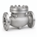
Stainless Steel Swing Check Valve
A bolted-cover check valve for preventing reverse flow in process and utility lines, engineered around flow velocity, orientation, pressure drop and transient behavior.
What is a stainless steel swing check valve?
A swing check valve contains a hinged disc that moves away from the seat as forward flow develops and returns toward the seat when flow decelerates or reverses. It operates automatically and normally has no manual operator.
Correct selection depends on more than line size. Minimum stable velocity, orientation, fluid density, pressure drop, pump behavior and system transients affect disc motion and slam risk. A check valve should be sized for operating flow conditions rather than automatically matching the pipe diameter.
Swing check valve specifications
| Product | Stainless steel swing check valve |
|---|---|
| Construction | Bolted cover; pressure-seal construction only when separately designed |
| Closure member | Hinged swing disc with service-specific hinge and pin arrangement |
| Body materials | ASTM A351 CF8/CF8M/CF3/CF3M; duplex or nickel alloy by specification |
| Trim and seating | Stainless/alloy trim with integral, renewable or hardfaced seats as ordered |
| Pressure rating | ASME Class or PN rating verified against material and temperature |
| End connections | RF, RTJ or butt-weld according to design |
| Installation | Horizontal or approved vertical-up flow only according to design |
| Optional features | External lever and weight, spring assist or dashpot only when engineered for the transient duty |
| Sizing inputs | Normal, minimum and maximum flow; fluid properties; differential pressure; line orientation and transient data |
| Documentation | Material records, pressure test report, GA drawing and inspection dossier as ordered |
The table describes typical engineered supply options, not a universal stock range. Final size, pressure-temperature rating, trim, seat, operator and end connection must be confirmed against the purchase specification and applicable code edition.
Stainless steel and alloy material options
| Material family | Common cast designations | Typical selection basis |
|---|---|---|
| Austenitic stainless steel | ASTM A351 CF8, CF8M, CF3 and CF3M | General corrosion resistance; CF8M/CF3M adds molybdenum for improved chloride resistance. |
| Duplex stainless steel | ASTM A995/A890 4A and related 2205 grades | Higher strength and improved chloride stress-corrosion resistance when properly specified. |
| Super duplex stainless steel | ASTM A995/A890 5A or 6A | Seawater, offshore and high-chloride service subject to temperature and fabrication controls. |
| Nickel alloy | ASTM A494 grades matching C276, Alloy 20, Monel or other ordered chemistry | Selected from actual process chemistry, concentration, temperature and contamination data. |
Design, testing and project compliance
API 594
Common design and testing basis for check valves within its scope, including flanged and butt-welding configurations.
ASME B16.34
Provides pressure-temperature, material, design, examination, testing and marking requirements within scope.
API 598
Common shell and closure pressure-testing basis when specified.
API 6D
Pipeline-service check valve requirements apply only when the valve is specifically designed, documented and ordered to API 6D.
Standards are supplied only when stated in the quotation and purchase order. Fire-safe, fugitive-emission, sour-service, cryogenic and PED requirements require a defined design and supporting qualification or documentation.
Typical applications
| Industry | Typical duty | Selection focus |
|---|---|---|
| Water and wastewater | Pump discharge and treatment lines | Stable velocity, slam control and solids content |
| Chemical processing | Process and transfer-system backflow prevention | Corrosion compatibility and minimum flow |
| Oil and gas | Pipeline and facility non-return duty | Transient analysis, API 6D scope and seat leakage |
| Marine and offshore | Cooling and utility systems | Duplex materials, orientation and galvanic compatibility |
Application examples are not a service approval. The end user or piping materials engineer must verify corrosion compatibility, pressure-temperature limits, emissions class, operating frequency and applicable regulations.
Inspection and supply documentation
EN 10204 3.1 material records and heat-number traceability when ordered.
Shell and closure/seat testing to the ordered standard with documented acceptance criteria.
Positive material identification and PT/RT/UT scope arranged when specified in the inspection plan.
Dimensions, marking, operation, coating/cleanliness, packing and document dossier checked before dispatch.
RFQ checklist
- Design standard and valve construction
- Nominal pipe size and pressure class or PN
- Body, cover, disc, hinge, pin, seat, bolting and gasket materials
- Normal, minimum and maximum flow rate
- Fluid density, viscosity, solids and operating temperature
- Line orientation and available straight run
- Pump trip or other transient information
- Closure leakage, NACE and inspection requirements
Frequently asked questions
Can a swing check valve be installed vertically?
Only when the design is approved for vertical upward flow and the operating velocity is sufficient to open and stabilize the disc. Vertical downward flow is generally unsuitable for a conventional swing check valve.
What causes check valve slam?
Rapid flow reversal, oversized valves, low velocity, excessive disc travel and system transients can cause impact during closure. Proper sizing and transient review are more effective than selecting by line size alone.
Does a swing check valve require an operator?
No. It normally opens and closes automatically with flow. External lever, weight, spring or dashpot arrangements are special engineered options rather than manual shutoff devices.
How should the valve be sized?
Use minimum, normal and maximum flow, fluid properties, pressure drop, orientation and transient behavior. A smaller nominal valve with stable disc position may perform better than a line-size valve in low-flow service.
When should an axial-flow check valve be considered?
An axial or nozzle check valve may be preferred where rapid non-slam closure, controlled disc travel or high cycling is important. The decision should follow hydraulic and transient analysis.
Request a swing check valve quotation
Provide the flow range, fluid, line orientation, pressure class, materials and transient information for technical selection.