

Tanım
İçerik Tablosu
- Specifications of 904L Stainless Steel Flanges
- Size Range of SS 904L Flanges (in Inches)
- Chemical Composition of ASME SA182 904L Weld Neck Raised Face Flanges
- Mechanical & Physical Characteristics of DIN 1.4539 904L flanşlar
- Variety of Industrial Flanges Made from UNS N08904 Paslanmaz çelik
- 904L Stainless Steel Flange Equivalent Grades and Standards
- Thermal Properties of DIN 1.4539 Ring-Type Joint Flanges
- Applications of Stainless Steel F904L Flanges
- Physical Parameters of 904L Stainless Steel Flanges
- Weight Chart for ASTM A182 F904L Long Weld Neck Flanges
- ANSI B16.5 F904L Ring Type Joint Flange Dimension Chart
- Pressure Rating Details for Stainless Steel F904L Weld Neck Flanges
Stainless Steel Flange
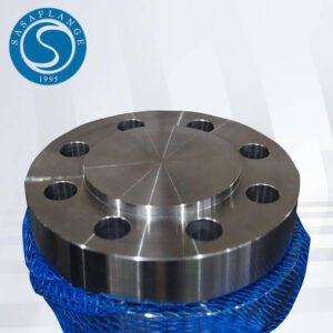
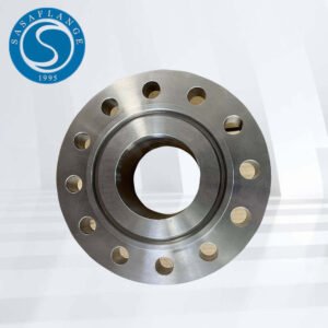
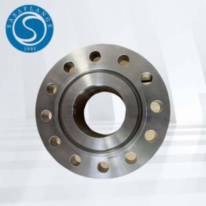
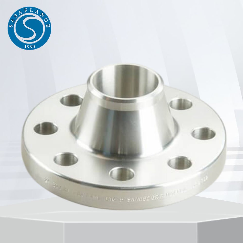
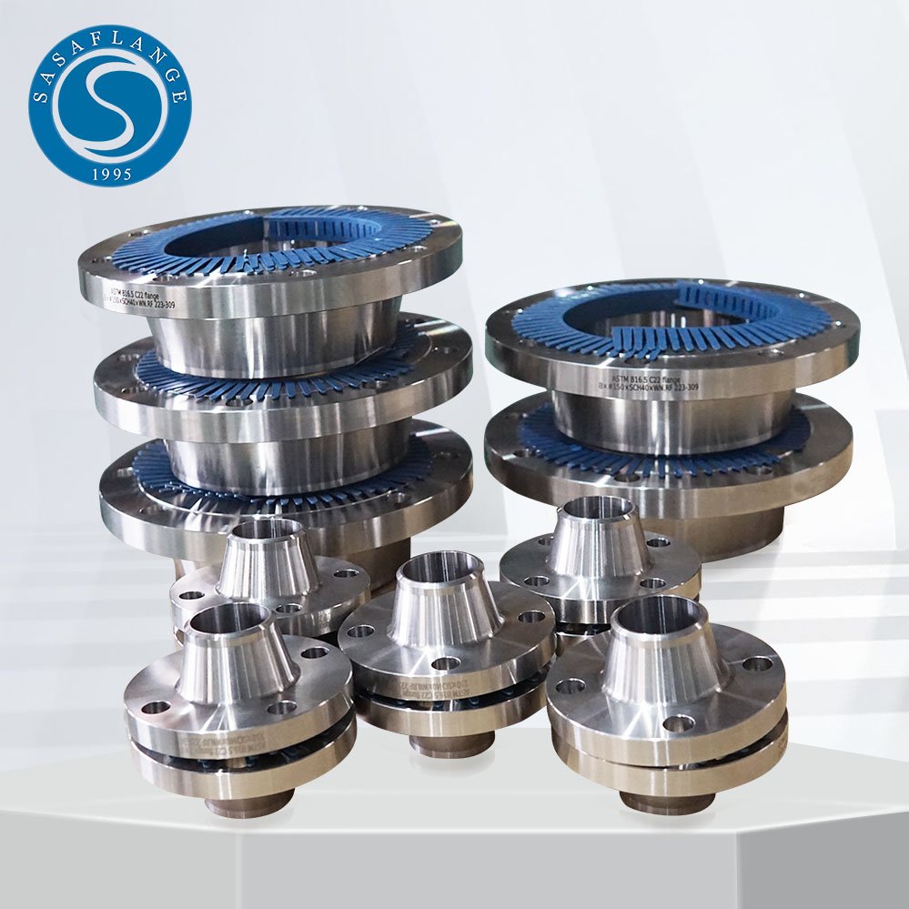
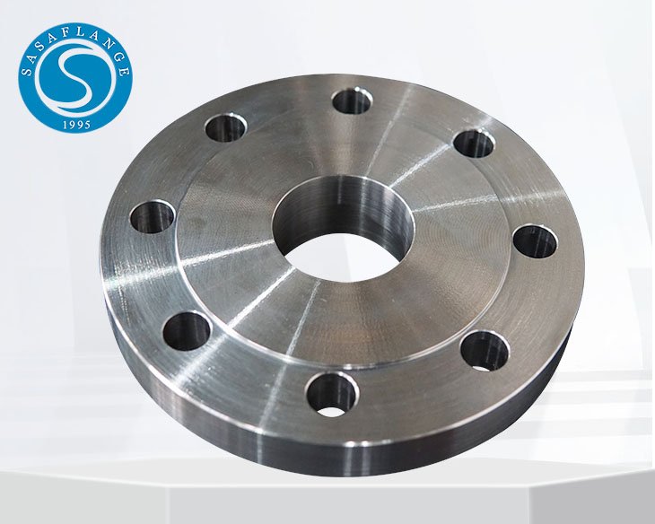
904L stainless steel flanges are high-alloy components designed for use in highly corrosive environments. Üretildiği yer UNS N08904 (DIN 1.4539), these flanges offer exceptional resistance to strong reducing acids such as sulfuric acid, as well as excellent performance against chloride-induced pitting and crevice corrosion. With low carbon content and added copper, 904L flanges maintain strength while preventing intergranular corrosion after welding. They are widely used in chemical processing, denizcilik uygulamaları, eczacılık, and pollution control equipment. Available types include weld neck, kör, bağcıksız, soket kaynağı, kucak eklemi, ve dişli flanşlar, conforming to standards such as ASTM A182 and ANSI B16.5. Their durability and corrosion resistance make them ideal for critical piping systems in aggressive environments.
Specifications of 904L Stainless Steel Flanges
| Özellikler | ASTM A182 / ASME SA182 |
|---|---|
| Sınıf | 150#, 300#, 600#, 900#, 1500#, 2500#, PN6, PN10, PN16, PN25, PN40, PN64 etc. |
| Boyut | 1/2″ (15 Not) to 48″ (1200Not) |
| Standartlar | ANSI/ASME B16.5, B16.48, BS4504, B 16.47 Series A & B, BS 10, EN-1092, DIN, vesaire. |
Size Range of SS 904L Flanges (in Inches)
| Nominal Boru Boyutu | Outside Diameter of Flange | Thickness of Flange | Diameter of Raised Face | Diameter of Hub at Base | Length Thru Hub | Diameter or Bore | Diameter of Hub at Bevel | Radius of Fillet | Depth of Socket | |||
|---|---|---|---|---|---|---|---|---|---|---|---|---|
| Welding Neck | Slip-On Threaded Socket | Kucak Bağlantısı | Slip-on Socket | Kucak Bağlantısı | ||||||||
| O | Q | R | X | Y | Y | Y | K | B | H | r | Z | |
| 1/2 | 3-1/2 | 7/16 | 1-3/8 | 1-3/16 | 1-7/8 | 5/8 | 5/8 | .88 | .90 | .84 | 1/8 | 3/8 |
| 3/4 | 3-7/8 | 1/2 | 1-11/16 | 1-1/2 | 2-1/16 | 5/8 | 5/8 | 1.09 | 1.11 | 1.05 | 1/8 | 7/16 |
| 1 | 4-1/4 | 9/16 | 2 | 1-15/16 | 2-3/16 | 11/16 | 11/16 | 1.36 | 1.38 | 1.32 | 1/8 | 1/2 |
| 1-1/4 | 4-5/8 | 5/8 | 2-1/2 | 2-5/16 | 2-1/4 | 13/16 | 13/16 | 1.70 | 1.72 | 1.66 | 3/16 | 9/16 |
| 1-1/2 | 5 | 11/16 | 2-7/8 | 2-9/16 | 2-7/16 | 7/8 | 7/8 | 1.95 | 1.97 | 1.90 | 1/4 | 5/8 |
| 2 | 6 | 3/4 | 3-5/8 | 3-1/16 | 2-1/2 | 1 | 1 | 2.44 | 2.46 | 2.38 | 5/16 | 11/16 |
| 2-1/2 | 7 | 7/8 | 4-1/8 | 3-9/16 | 2-3/4 | 1-1/8 | 1-1/8 | 2.94 | 2.97 | 2.88 | 5/16 | 3/4 |
| 3 | 7-1/2 | 15/16 | 5 | 4-1/4 | 2-3/4 | 1-3/16 | 1-3/16 | 3.57 | 3.60 | 3.50 | 3/8 | 13/16 |
| 3-1/2 | 8-1/2 | 15/16 | 5-1/2 | 4-13/16 | 2-13/16 | 1-1/4 | 1-1/4 | 4.07 | 4.10 | 4.00 | 3/8 | 7/8 |
| 4 | 9 | 15/16 | 6-3/16 | 5-5/16 | 3 | 1-5/16 | 1-5/16 | 4.57 | 4.60 | 4.50 | 7/16 | 15/16 |
| 5 | 10 | 15/16 | 7.5/16 | 6-7/16 | 3-1/2 | 1-7/16 | 1-7/16 | 5.66 | 5.69 | 5.56 | 7/16 | 15/16 |
| 6 | 11 | 1 | 8-1/2 | 7-9/16 | 3-1/2 | 1-9/16 | 1-9/16 | 6.72 | 6.75 | 6.63 | 1/2 | 1-1/16 |
| 8 | 13-1/2 | 1-1/8 | 10-5/8 | 9-11/16 | 4 | 1-3/4 | 1-3/4 | 8.72 | 8.75 | 8.63 | 1/2 | 1-1/4 |
| 10 | 16 | 1-3/16 | 12-3/4 | 12 | 4 | 1-15/16 | 1-15/16 | 10.88 | 10.92 | 10.75 | 1/2 | 1-5/16 |
| 12 | 19 | 1-1/4 | 15 | 14-3/8 | 4-1/2 | 2-3/16 | 2-3/16 | 12.88 | 12.92 | 12.75 | 1/2 | 1-9/16 |
| 14 | 21 | 1-3/8 | 16-1/4 | 15-3/4 | 5 | 2-1/4 | 3-1/8 | 14.14 | 14.18 | 14.00 | 1/2 | 1-5/8 |
| 16 | 23-1/2 | 1-7/16 | 18-1/2 | 18 | 5 | 2-1/2 | 3-7/16 | 16.16 | 16.19 | 16.00 | 1/2 | 1-3/4 |
| 18 | 25 | 1-9/16 | 21 | 19-7/8 | 5-1/2 | 2-11/16 | 3-13/16 | 18.18 | 18.20 | 18.00 | 1/2 | 1-15/16 |
| 20 | 27-1/2 | 1-11/16 | 23 | 22 | 5-11/16 | 2-7/8 | 4-1/16 | 20.20 | 20.25 | 20.00 | 1/2 | 2-1/8 |
| 24 | 32 | 1-7/8 | 27-1/4 | 26-1/8 | 6 | 3-1/4 | 4-3/8 | 24.25 | 24.25 | 24.00 | 1/2 | 2-1/2 |
Chemical Composition of ASME SA182 904L Weld Neck Raised Face Flanges
| Seviye | C | Mn | Ve | P | S | CR | Ay | İçinde | Cu |
| SS 904L | 0.020 maksimum | 2 maksimum | 1.00 maksimum | 0.040 maksimum | 0.030 maksimum | 19.00 – 23.00 | 4.00 – 5.00 maksimum | 23.00 – 28.00 | 1.00 – 2.00 |
Mechanical & Physical Characteristics of DIN 1.4539 904L flanşlar
| Yoğunluk | Erime Noktası | Çekme Dayanımı | Akma Dayanımı (0.2%Telafi etmek) | Uzama |
| 7.95 g/cm3 | 1350 °C (2460 °F) | Psi – 71000 , MPa – 490 | Psi – 32000 , MPa – 220 | 35 % |
Variety of Industrial Flanges Made from UNS N08904 Paslanmaz çelik
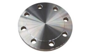 | 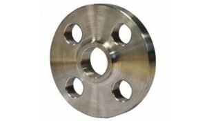 | 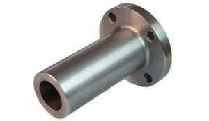 | 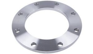 |
| Kör flanşlar | Bindirme Bağlantı Flanşları | Uzun Kaynak Boyunlu Flanşlar | Plaka Flanşları |
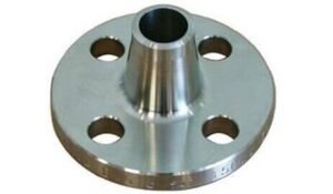 | 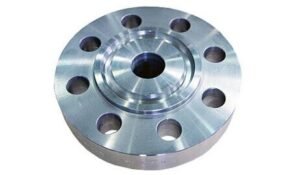 | 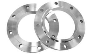 | 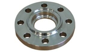 |
| Flanşların Azaltılması | Ring Type Joint Flanges | Flanşlarda Kayma | Soket Kaynaklı Flanşlar |
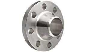 | 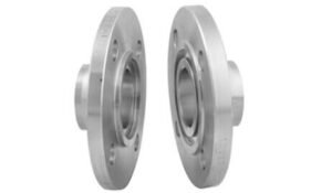 | 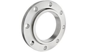 | 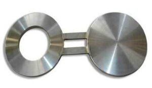 |
| Kaynak Boyunlu Flanşlar | Tongue & Groove Flanges | Dişli / Screwed Flanges | Gözlük Kör Flanşları |
904L Stainless Steel Flange Equivalent Grades and Standards
| STANDART | MALZEME NO. | BİZ | JIS | BS | KS | AFNOR | EN |
| SS 904L | 1.4539 | N08904 | SUS 904L | 904S13 | STS 317J5 | Z2 NCDU 25-20 | X1NiCrMoCu25-20-5 |
Thermal Properties of DIN 1.4539 Ring-Type Joint Flanges
DIN 1.4539, also known as Alloy 904L or UNS N08904, is an austenitic stainless steel designed for exceptional corrosion resistance, particularly in aggressive environments. When used in Halka Tipi Bağlantı (RTJ) flanşlar, its thermal properties are critical for ensuring sealing performance and dimensional stability under varying temperature conditions.
| Property | Value | Notes |
|---|---|---|
| Thermal Conductivity (at 20°C) | ~12.0 W/m·K | Lower than carbon steel, typical of austenitic SS |
| Specific Heat Capacity (at 20°C) | ~500 J/kg·K | High thermal inertia, suitable for stable operation |
| Coefficient of Thermal Expansion | ~16.5 µm/m·K (from 20–100°C) | Important for gasket fit in RTJ sealing surfaces |
| Melting Range | 1300 – 1390°C | Indicates safe upper limit for high-temp service |
| Maximum Continuous Service Temp | ~400°C (in oxidizing environments) | Beyond this, corrosion resistance may reduce |
| Thermal Shock Resistance | Ilıman | Preheating and slow cooling are recommended in cyclic heating scenarios |
These thermal characteristics make DIN 1.4539 RTJ flanges ideal for high-temperature, high-pressure sealing applications in chemical processing, rafineri, and offshore installations, where thermal cycling and aggressive media are present. Proper design allowances for expansion and thermal stress are essential to maintain joint integrity.
Applications of Stainless Steel F904L Flanges
Chemical Processing Plants
Resistant to strong acids such as sulfuric, phosphoric, ve asetik asitler, 904L weld neck flanges are ideal for piping systems handling corrosive fluids.Yağ & Gaz Rafinerileri
Used in offshore and onshore installations, especially where resistance to chloride-induced stress corrosion cracking is required.Tuzdan Arındırma Tesisleri
Excellent performance in high-chloride environments makes them suitable for seawater treatment and desalination piping systems.İlaç & Food Processing Industries
Non-reactive and hygienic surface properties make F904L flanges suitable for clean-in-place (CIP) systems and sterile fluid pipelines.Kağıt hamuru & Paper Industry
Used in bleach plants and acidic process lines due to their resistance to oxidizing media.Gemi Mühendisliği
Preferred in shipbuilding and offshore platforms due to their durability in saline water environments.Pollution Control Equipment
Employed in flue gas desulfurization (OGG) sistemler, especially in scrubber assemblies and acid gas lines.
Physical Parameters of 904L Stainless Steel Flanges
| Property | Value | Tanım |
|---|---|---|
| Yoğunluk | 8.0 g/cm³ (8000 kg/m³) | High-density material suitable for pressure retention |
| Modulus of Elasticity | ~200 GPa (at 20°C) | Indicates good rigidity and deformation resistance |
| Poisson’s Ratio | ~0.30 | Ratio of lateral to axial strain |
| Thermal Conductivity | ~12 W/m·K (at 20°C) | Lower than carbon steel; affects heat dissipation rate |
| Specific Heat Capacity | ~500 J/kg·K (at 20°C) | Reflects energy required to raise temperature |
| Electrical Resistivity | ~0.95 µΩ·m | Higher than common stainless grades, reducing galvanic effects |
| Magnetic Permeability | ~1.0 (non-magnetic in annealed condition) | Suitable for non-magnetic applications |
| Melting Range | 1300 – 1390°C | Relevant for welding and high-temperature environments |
Weight Chart for ASTM A182 F904L Long Weld Neck Flanges
Not: The actual weight may vary slightly depending on exact dimensions, flanş kalınlığı, neck length, and manufacturing tolerances.
| Pipe Normal Diam. | O.D. Flanş | Thk. Of Flange Min | Diam. ile ilgili Hub | Diameter of Raised Face | Length Hub.Y | Thread Length | Diam. of Bolt Circle | Diam. of Bolt Holes | Number of Bolts | Diam. ile ilgili Cıvatalar (inç) | KG | LB | |
|---|---|---|---|---|---|---|---|---|---|---|---|---|---|
| inç | dn | O | C | X | G | Y | T | BC | BH | BN | BD | ||
| 1/2″ | 15 | 89.00 | 11.20 | 30.20 | 35.10 | 15.70 | 15.70 | 60.50 | 15.80 | 4 | 1/2″ | 0.4 | 0.9 |
| 3/4″ | 20 | 98.50 | 12.70 | 38.10 | 42.90 | 15.70 | 15.70 | 69.90 | 15.80 | 4 | 1/2″ | 0.7 | 1.5 |
| 1″ | 25 | 108.00 | 14.20 | 49.30 | 50.80 | 17.50 | 17.50 | 79.30 | 15.80 | 4 | 1/2″ | 0.8 | 1.8 |
| 1-1/4″ | 32 | 117.50 | 15.70 | 58.70 | 63.50 | 20.60 | 20.60 | 88.90 | 15.80 | 4 | 1/2″ | 1.2 | 2.6 |
| 1-1/2″ | 40 | 127.00 | 17.50 | 65.00 | 73.20 | 22.40 | 22.40 | 98.60 | 15.80 | 4 | 1/2″ | 1.5 | 3.3 |
| 2″ | 50 | 152.50 | 19.10 | 77.70 | 91.90 | 25.40 | 25.40 | 120.70 | 19.10 | 4 | 5/8″ | 2.3 | 5.1 |
| 2-1/2″ | 65 | 178.00 | 22.40 | 90.40 | 104.60 | 28.40 | 28.40 | 139.70 | 19.10 | 4 | 5/8″ | 3.7 | 8.1 |
| 3″ | 80 | 190.50 | 23.90 | 108.00 | 127.00 | 30.20 | 30.20 | 152.40 | 19.10 | 4 | 5/8″ | 4.1 | 9 |
| 3-1/2″ | 90 | 216.00 | 23.90 | 122.20 | 139.70 | 31.80 | 31.80 | 177.80 | 19.10 | 8 | 5/8″ | 5.1 | 11.2 |
| 4″ | 100 | 228.50 | 23.90 | 134.90 | 157.20 | 33.30 | 33.30 | 190.50 | 19.10 | 8 | 5/8″ | 5.9 | 13 |
| 5″ | 125 | 254.00 | 23.90 | 163.60 | 185.70 | 36.60 | 36.60 | 215.90 | 22.40 | 8 | 3/4″ | 7 | 15.4 |
| 6″ | 150 | 279.50 | 25.40 | 192.00 | 215.90 | 39.60 | 39.60 | 241.30 | 22.40 | 8 | 3/4″ | 8.4 | 18.5 |
| 8″ | 200 | 343.00 | 28.40 | 246.10 | 269.70 | 44.50 | 44.50 | 298.50 | 22.40 | 8 | 3/4″ | 13 | 28.6 |
| 10″ | 250 | 406.50 | 30.20 | 304.80 | 323.90 | 49.30 | 49.30 | 362.00 | 25.40 | 12 | 7/8″ | 18 | 39.5 |
| 12″ | 300 | 482.50 | 31.80 | 365.30 | 381.00 | 55.60 | 55.60 | 431.80 | 25.40 | 12 | 7/8″ | 29 | 64 |
| 14″ | 350 | 533.50 | 35.10 | 400.10 | 412.80 | 57.20 | 57.20 | 476.30 | 28.50 | 12 | 1″ | 39 | 86 |
| 16″ | 400 | 597.00 | 36.60 | 457.20 | 469.90 | 63.50 | 63.50 | 539.80 | 28.50 | 16 | 1″ | 47 | 103 |
| 18″ | 450 | 635.00 | 39.60 | 505.00 | 533.40 | 68.30 | 68.30 | 577.90 | 31.80 | 16 | 1 1/8″ | 57 | 126 |
| 20″ | 500 | 698.50 | 42.90 | 558.80 | 584.20 | 73.20 | 73.20 | 635.00 | 31.80 | 20 | 1 1/8″ | 76 | 167 |
| 24″ | 600 | 813.00 | 47.80 | 663.40 | 692.20 | 82.60 | 82.60 | 749.30 | 35.10 | 20 | 1 1/4″ | 97 | 214 |
ANSI B16.5 F904L Ring Type Joint Flange Dimension Chart
Malzeme: ASTM A182 F904L (UNS N08904, DIN 1.4539)
Unit: mm (millimeters), unless noted
| Standart | Sınıf | Çap | Bolt Circle Diameter | Number of Bolts | Cıvata Boyutu | Diameter of Bolt Hole |
|---|---|---|---|---|---|---|
| AS4087 | PN14 | 95 | 67 | 4 | M12 | 14 |
| GİBİ 2129 Flanş | Table C | 95 | 67 | 4 | 13 | 14 |
| Table D | 95 | 67 | 4 | 13 | 14 | |
| Table E | 95 | 67 | 4 | 13 | 14 | |
| Table F | 95 | 67 | 4 | 13 | 14 | |
| Table H | 114 | 83 | 4 | 16 | 17 | |
| Table J | 114 | 83 | 4 | 16 | 17 | |
| ANSI B16.5 | ANSI 150 | 89 | 60 | 4 | 13 | 16 |
| ANSI 300 | 95 | 67 | 4 | 13 | 16 | |
| ANSI 600 | 95 | 67 | 4 | 13 | 16 | |
| ANSI 900 | 121 | 83 | 4 | 19 | 22 | |
| ANSI 1500 | 121 | 83 | 4 | 19 | 22 | |
| ISO 7005 (DIN) Flanş | PN6 | 80 | 55 | 4 | M10 | 11 |
| PN10 | 95 | 65 | 4 | M12 | 14 | |
| PN16 | 95 | 65 | 4 | M12 | 14 | |
| PN20 | 90 | 60.5 | 4 | M14 | 16 | |
| PN25 | 95 | 65 | 4 | M12 | 14 | |
| PN40 | 95 | 65 | 4 | M12 | 14 |
Pressure Rating Details for Stainless Steel F904L Weld Neck Flanges
| Flange Class | Max Pressure @ 100°F (38°C) | Max Pressure @ 200°F (93°C) | Max Pressure @ 400°F (204°C) |
|---|---|---|---|
| Sınıf 150 | 285 psi (19.6 çubuk) | 235 psi (16.2 çubuk) | 170 psi (11.7 çubuk) |
| Sınıf 300 | 740 psi (51.0 çubuk) | 605 psi (41.7 çubuk) | 460 psi (31.7 çubuk) |
| Sınıf 600 | 1480 psi (102.0 çubuk) | 1210 psi (83.4 çubuk) | 920 psi (63.4 çubuk) |
| Sınıf 900 | 2220 psi (153.1 çubuk) | 1815 psi (125.1 çubuk) | 1380 psi (95.1 çubuk) |
| Sınıf 1500 | 3705 psi (255.4 çubuk) | 3025 psi (208.5 çubuk) | 2295 psi (158.3 çubuk) |
| Sınıf 2500 | 6170 psi (425.3 çubuk) | 5040 psi (347.6 çubuk) | 3825 psi (263.8 çubuk) |
Key Notes:
These ratings apply to F904L weld neck flanges manufactured in accordance with ASME B16.5 using ASTM A182 F904L forging material.
904L has excellent corrosion resistance, especially in acidic and chloride-rich environments, making it suitable for high-pressure chemical and marine systems.
Actual operating pressure should also consider factors like gasket type, bolt torque, flange face finish, and system design.
If you need pressure ratings at higher temperatures (örneğin, 600°F or 800°F), or want EN 1092-1 PN rating equivalents, I can provide that as well.